
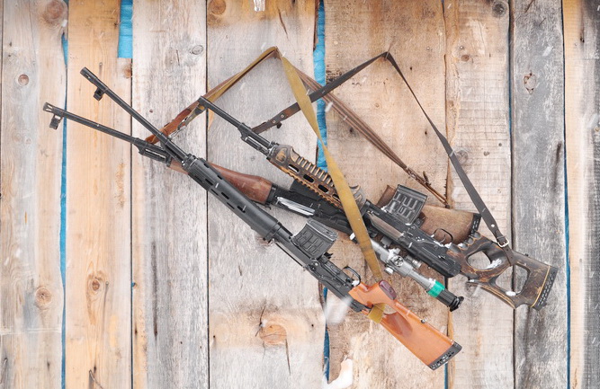
SVD – sniper “whip”. sniper rifle svd
Sniper rifle Dragunov It has been in service since 1963 and, apparently, they do not intend to change it for something else. Despite the fact that this weapon is already quite old, it still copes with the tasks that face it, although many are of the opinion that this weapon is already outdated and urgently needs to be changed. Let's try to figure out whether this model of rifle is so outdated, and whether it is worth looking for a replacement, given that there are more pressing gaps in the weapons of both the army and the police. At the same time, let’s briefly go over the design of this weapon, since for many, as it turns out, it is unknown in its structure.

At the end of the fifties, namely in 1958, the Main Rocket and Artillery Directorate (GRAU) formulated a task for designers to create a new self-loading sniper rifle for Soviet Army. The following took part in the competition: famous designers like Kalashnikov, Barinov, Konstantinov and, naturally, Dragunov. Weapons from other designers will be discussed in separate articles, especially since the samples presented were quite interesting. For a sniper rifle, in the usual understanding of most people, the basic requirements that were set before the designers were not entirely clear.
Thus, the weapon was required to be able to confidently fire at the enemy at a distance of only 600 meters, that is, at this distance the enemy had to be guaranteed to be hit from this weapon. But now it is fashionable to talk about weapons that shoot at 1000 meters and further, but they usually forget that the distances for accurate fire in combat, even in open areas, are much shorter for a sniper who works as part of a unit. In other words, he has completely different tasks, or rather their implementation, in comparison with those of a sniper crew working separately.
Naturally, for someone who needs to hit a target at a distance of 1500 meters, the SVD will be a completely unsuitable weapon, but these snipers are not armed with such rifles. Consequently, the SVD copes with its tasks, and given the weapon’s unpretentiousness to operating conditions, ease of maintenance and well-established production, it makes no sense to change this weapon.

For example, you can look at those that stand on at the moment in service in other armies of other countries. Despite the fact that more accurate and long-range models are being adopted, no one is in a hurry to abandon weapons similar in their characteristics to the SVD, and they coexist quite peacefully with long-range and accurate models.
Of course, we would like to see a more advanced weapon, with higher performance, light and compact, but no one will allocate funds to remove the rifle from service one day and replace it with another model. And this problem is not so acute as to make a fuss about it. It would be more reasonable to work with weapon ammunition in order to increase its armor-piercing properties; this is both cheaper and more relevant at the moment, and only after that make weapons based on it.

What exactly is SVD? This is a self-loading rifle, the automation of which is based on the use of powder gases diverted from the bore of the weapon and with the barrel bore being locked when the bolt is turned to 3 lugs. The weapon is fed from a detachable box magazine with a capacity of 10 rounds of 7.62x54R ammunition. For firing from the SVD, rifle cartridges with ordinary, tracer and armor-piercing incendiary bullets, as well as sniper cartridges (7N1, 7N14) are used. The SVD can also fire JHP and JSP hollow-point bullets.
The weight of the weapon without ammunition is 4.2 kg with a total rifle length of 1220 mm. Barrel length – 620 mm. Initial speed bullets 830 m/s. Muzzle energy of a bullet 4064 Joule. Quite often the design of the rifle is compared with the design of the Kalashnikov assault rifle, however, despite the same basic points, this weapon has its own characteristics.

First of all, it should be noted that the gas piston is not rigidly connected to the bolt frame, which reduces the overall weight of the moving parts of the weapon when firing. In addition, the barrel bore is locked by three lugs (one of which is a rammer) when the bolt is turned counterclockwise. The trigger mechanism of a hammer-type weapon is assembled in one housing.
The weapon's safety is controlled by a fairly large lever on the right side of the rifle. In the on position, the safety locks the trigger and also limits the rearward movement of the bolt frame, which provides protection from external contamination during transportation. The rifle's flash hider also serves as a muzzle brake-recoil compensator, although it is difficult to give an example when this is not the case. The flame arrester has five slotted slots. The forend and butt of the weapon were previously made of wood, now of plastic. A non-adjustable cheek rest for the shooter is installed on the butt.

The Dragunov sniper rifle has both open sights and a seat for various sights. In addition to the optical sight, various night sights can be installed on the weapon; with such a sight, the SVD turns into an SVDN. In case the optical sight fails, the shooter can continue to perform his tasks using open sights, which consist of an adjustable rear sight mounted in front of the receiver cover and a front sight in the front sight.
The SVD has high accuracy for a weapon of this type. With the SVD sniper cartridge, you can hit the following targets with the first shot:
head - 300 m
chest figure - 500 m
waist figure - 600 m
running figure - 800 m.
The PSO-1 sight is designed for shooting up to 1300 meters, but at such a range you can only effectively shoot at a group target, or conduct harassing fire.

Let's try to briefly describe how this whole thing works. When fired, the powder gases push the bullet forward along the barrel bore, reaching the hole in the barrel to remove the powder gases, they enter the gas engine and push the piston back. Having accelerated the bolt frame, the piston stops. The frame, in the process of its movement back, turns the bolt, which unlocks the bore, removes and throws out the spent cartridge case. Actually, this is how quite satisfactory firing performance is achieved simply and without any supernatural nuances.

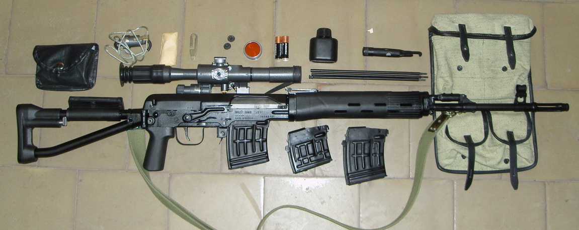
 Dragunov sniper rifle with folding stock (SVDS)
 Azerbaijani Armed Forces
 Armed Forces of Armenia
 Bolivian Armed Forces
Of course, no one will argue that military-made remakes are completely unsuitable by their very concept as hunting weapons, and it is always better what was created specifically in targeted projects. However, like AKM-oid carbines such as Saiga, Vepr and others, the Tiger is for the most part a tribute to the military conscription past of every Russian hunter, the mentality of the nation, and the current lack of its own sane hunting weapons production in Russia in this class.
But it is precisely the simplicity and reliability of our carbines, their ultimate design, that primarily attracts the domestic hunter. The excessive complexity of imported weapons once again makes us recall the axiom of weapons designers - the most difficult thing is to create a simple, and therefore reliable and most technologically advanced system. And since two unique technologies are used in the production of SVDs, this makes itself felt for any purpose of this weapon. The only question is why you need it.
The history of the creation of the Tiger hunting rifle
The self-loading sniper rifle by Evgeniy Dragunov replaced the outdated three-line sniper rifle back in 1963. The need for such weapons has been recognized for a long time. And in 1958, the GRAU of the General Staff of the SA announced a competition to create a self-loading sniper rifle for the Soviet Army, formulating difficultly compatible requirements in the terms of reference.
The military's demands were strict and included the following: the rifle must be chambered for a standard three-line cartridge, self-loading, not inferior in reliability to the AKM, have a replaceable box magazine for 10 rounds, and in terms of weight and size parameters correspond to a three-line sniper. It must be taken into account that the SVD is not a sniper rifle in the full sense; its main purpose is to increase the effective fire range of a motorized rifle squad to 600 m and provide the necessary rifle support. The accuracy characteristic of a police or sporting rifle was not initially included in the SVD, and this must be understood when planning to use the Tiger for accurate shooting at maximum distances.
Dragunov was able to successfully combine excellent shooting accuracy, maneuverability and maximum resistance to adverse combat conditions in the new rifle created under his leadership. The production of the rifle was located at IZHMASH. To this day, the SVD remains a tool that allows solving standard sniper tasks in combined arms combat.
The main part of the automatic rifle is the bolt frame, which receives the effects of powder gases through a separate gas piston and pusher. Automation parts have a low mass and low energy in extreme positions, which ensures minimal deflection of the rifle when fired and quick restoration of aiming. The reloading handle is integral with the bolt frame. Rifle return mechanism with two coil springs. The trigger mechanism allows only single fire. Flag fuse, double action. It simultaneously locks the trigger and limits rearward movement of the bolt carrier. The trigger is assembled in a separate removable housing and ensures that a shot is fired only when the bolt is completely locked. It is generally impossible to assemble the SVD incorrectly, which is an important factor. When all the cartridges in the magazine are used up, the shutter is delayed.
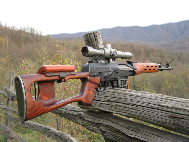
Hunting carbine TIGER- a hunting modification of the famous army Dragunov rifle (SVD). The Tiger uses the same inexpensive rifle cartridges, only equipped with semi-jacketed bullets, and are marked “7.62x54 R”. "Tiger" and "Tiger-1"- a self-loading hunting carbine of 7.62 mm caliber chambered for the 7.62x53 (7.62x54R) hunting cartridge with a semi-jacketed bullet weighing 13 g. According to the passport, it is intended for hunting medium and large animals.

The Tiger carbine appeared in the late 70s. Prototypes carbines were created under the leadership of E.F. Dragunov in 1969. The basic model was the famous domestic Dragunov rifle - SVD. It is manufactured in two modifications: “Tiger” and “Tiger-1”. In 1996, an export (Americanized) version of the Tiger-1 was created.
Design of the Tiger hunting rifle
The Tiger self-loading carbine is as unpretentious as its parent (SVD), easy to operate and clean. The rate of fire and automation are not satisfactory. I was very pleased with the opportunity to fire from an open sight without removing the optics.
But during actual operation, not everything turned out to be so rosy:
- army sight PSO-1 - turned out to be not suitable for hunting needs;
- orthopedic butt - very inconvenient for a hunter;
- the first version of the “Tiger” was made with plastic linings on the fore-end, this of course makes the design of the carbine easier, but shooting in the cold threatens frostbite on your fingers, and they creak in the cold;
- the absence of a flame arrester as such makes it blind when fired at dusk.
According to the legislation of a number of countries (USA, England, France), the import of weapons that have an external resemblance to combat systems is prohibited. In the USA, for example, imported long-barreled firearms must not have two of the following features of a military weapon: a detachable magazine with a capacity of more than 10 rounds, a bayonet attachment point, ventilation holes in the barrel linings, the front sight must only be open, the digitization of the sighting bar must be more than 5 divisions.Therefore, when in 1996 the question of lifting restrictions (introduced in 1993) on the export of Russian sporting and hunting weapons to the American market was once again raised, a new export version of the Tiger was prepared.
Manufacturers of the carbine took into account the requirements of foreign legislation and numerous complaints from their own consumers, and released another modification of the Tiger, calling it "Tiger-1".
The carbine was modified more carefully:
- universal side mounts have appeared for most hunting optical sights;
- added a muzzle brake-flash suppressor, which quite significantly reduces recoil and blinding from the flash;
- the butt was changed, a “pistol grip” was added, a comb on top for easier aiming;
- expanded the possibilities of moving the front sight when sighting.
"Tiger" carbines have modifications for the following cartridges (all modifications can also be produced in a non-self-loading version):
- Tiger Self-loading hunting carbine chambered for 7.62x54R;
- Tiger-308 Self-loading hunting carbine chambered for 308Win (7.62x51);
- Tiger-30-06 Self-loading hunting carbine chambered for 30-06Sprg (7.62x63)
- Tiger-9 Self-loading hunting carbine chambered for 9.3x64 cartridge.
The characteristics of the cartridges used are given in the table. To ensure safety when shooting, only certified cartridges should be used.
Automatic reloading of the carbine occurs due to the energy of the powder gases removed from the barrel bore into the gas chamber, and the energy of the return springs. The bolt is locked onto three lugs by rotating the bolt around its axis while sliding the frame longitudinally. The hammer-type trigger mechanism ensures the production of single shots and setting the safety.
The flag-type fuse is located on the right side of the receiver. The trigger mechanism is made detachable. The bore and chamber are chrome plated. The drummer is spring loaded.
The butt and receiver linings are made of wood (walnut, beech, birch) or impact-resistant plastic. Wooden stock with rubber butt.
The open sight consists of an aiming bar and a front sight that is adjustable in two planes. The aimed shooting range with an open sight is 300m.
On the left side of the carbine receiver there is a unified base for mounting an optical sight. Targeted shooting from an open sight can be carried out without removing the optical sight.
The technology for manufacturing SVD and Tiger barrels is unique and is not used anywhere else. First, the barrel blank undergoes deep drilling under high oil pressure. After which the resulting channel is subjected to double scanning. The resulting smooth channel is further polished using an electric discharge.
After which comes the most interesting stage in the manufacture of a barrel for the Tiger: electrical erosion. The barrel blank is placed in a special solution. A tool with an exact copy of the rifling is inserted into the channel. Under the influence of an electric discharge, the smooth surface of the barrel bore acquires an exact copy of the geometry of the tool. Figuratively speaking, the “extra” metal is “washed out”, forming rifling. Of course, it is difficult to imagine how so much metal can be removed in this way, but this is the uniqueness of the technology.
An almost finished barrel, with rifling already formed, is subjected to turning of the outer surface, where it is given the desired geometry. This is followed by heat treatment of the barrel. Then the barrel bore undergoes an operation unusual for sniper barrels - chrome plating.
.jpg)
Only lazy people haven’t written about the negative role of chrome coating, but for military weapons, a chrome-plated barrel bore greatly makes life easier for a soldier. Moreover, some copies of SVD and Tigers issue “minute” groups without any problems, which is more than enough for weapons of this class. In any case, despite the accuracy standard of 80 mm at 100 m, the average results of the SVD and the Tiger at this distance are 50-60 mm. More than enough for hunting.
The rifle barrel has 4 grooves. The rifling stroke length is 240 or 320 mm. The barrel length of the SVD and the long Tiger is 620 mm. “Short” “Tigers” have a 530 mm barrel. The barrel life is stated to be 6000 shots.
Modifications of the Tiger hunting rifle
Tiger with folding stock, Tiger with hunting stock, Tiger with plastic stock, Tiger-308, Tiger-9
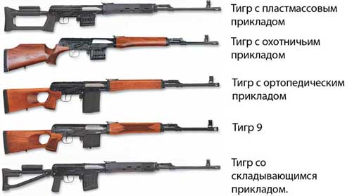
Tiger Self-loading hunting carbine with an orthopedic butt and wooden barrel guards
|
Caliber, mm |
Cartridge used |
Magazine capacity |
Barrel length, mm |
Total length, mm |
Weight, kg |
Tiger in Spanish 01 A carbine with a plastic butt of the “SVD type” with a rotating cheekpiece and plastic linings.
|
Caliber, mm |
Cartridge used |
Magazine capacity |
Barrel length, mm |
Total length, mm |
Weight, kg |
Tiger in Spanish 02 A carbine with a folding metal stock of the “SVDS type” with a rotating cheekpiece and plastic or wooden pads.
|
Caliber, mm |
Cartridge used |
Magazine capacity |
Barrel length, mm |
Weight, kg |
|
Tiger in Spanish 03 A carbine with a hunting wooden butt and wooden or plastic pads.
|
Caliber, mm |
Cartridge used |
Magazine capacity |
Barrel length, mm |
Total length, mm |
Weight, kg |
Tiger isp.05 The carbine, made in a design that is as close as possible to the appearance of the SVD rifle, is equipped with a plywood butt with a detachable cheekpiece, plywood barrel linings with ventilation holes, a gas tube with a regulator, a 1200 m sighting bar, and a front sight base with an extended flash suppressor.
|
Caliber, mm |
Cartridge used |
Magazine capacity |
Barrel length, mm |
Total length, mm |
Weight, kg |
Tiger-308 Self-loading hunting carbine chambered for the popular 308Win cartridge (7.62x51) with an orthopedic stock and wooden barrel guards.
|
Caliber, mm |
Cartridge used |
Magazine capacity |
Barrel length, mm |
Total length, mm |
Weight, kg |
|
308 Win(7.62x51) |
Tiger-308 isp. 01 Carbine with a stationary hunting butt and wooden overlays.
|
Caliber, mm |
Cartridge used |
Magazine capacity |
Barrel length, mm |
Total length, mm |
Weight, kg |
|
308 Win(7.62x51) |
Tiger-308 isp. 02 A carbine with a buttstock with a rotating cheekpiece of the SVD type and plastic linings.
|
Caliber, mm |
Cartridge used |
Magazine capacity |
Barrel length, mm |
Total length, mm |
Weight, kg |
|
308 Win(7.62x51) |
Tiger-308 isp. 03 A carbine with a control handle, with a folding metal stock of the SVDS type with a rotating cheekpiece and plastic linings.
|
Caliber, mm |
Cartridge used |
Magazine capacity |
Barrel length, mm |
Overall length/length with folding stock, mm |
Weight, kg |
|
308 Win(7.62x51) |
Tiger-30-06 Self-loading hunting carbine chambered for 30-06Sprg (7.62x63) with an orthopedic stock and wooden barrel guards.
|
Caliber, mm |
Cartridge used |
Magazine capacity |
Barrel length, mm |
Total length, mm |
Weight, kg |
Tiger-30-06 isp.01 A carbine with a hunting stock and wooden barrel linings.
|
Caliber, mm |
Cartridge used |
Magazine capacity |
Barrel length, mm |
Total length, mm |
Weight, kg |
Tiger-30-06 isp.02 A carbine with a plastic butt with a rotating cheekpiece of the SVD type and plastic barrel linings.
|
Caliber, mm |
Cartridge used |
Magazine capacity |
Barrel length, mm |
Total length, mm |
Weight, kg |
Tiger-9 Self-loading hunting carbine chambered for 9.3x64 cartridge with an orthopedic stock and wooden barrel linings. Magazine capacity
Barrel length, mm
Total length, mm
Weight, kg
565 or 620 Caliber, mm
Cartridge used
Magazine capacity
Barrel length, mm
Total length, mm
Weight, kg
Barrel length, mm
Total length, mm
Weight, kg
565 or 620 Caliber, mm
Cartridge used
Magazine capacity
Barrel length, mm
Total length, mm
Weight, kg
|
Caliber, mm |
Cartridge used |
Magazine capacity |
Barrel length, mm |
Total length, mm |
Weight, kg |
Carbines of all modifications have different versions of the main components.
Butt design options:
- Orthopedic wooden butt (with cutout for thumb);
- Hunting stock. In this case, the trigger is made slightly pulled back;
- Plastic stock of the OVD type. For ease of shooting from an optical sight, there is a rotating cheekpiece;
- Right side folding tubular metal stock and pistol grip. The buttstock is equipped with a rotating cheekpiece for convenience when shooting from an optical sight. The length of the carbine with the stock folded is reduced by 260 mm.
- Wooden hunting;
- Plastic;
- With long cylindrical flame arrester;
- With short conical flame arrester;
- No flame arrester.
The mandatory delivery set for carabiners includes: a cleaning rod, accessories in a pencil case, and an oiler. By special order, carbines can be equipped with an optical sight with a bracket, as well as a case and a belt.
Technical characteristics of carbines
| Tiger | Tiger-308 | Tiger-9 | |
| Caliber, mm | 7,62 | 7,62 | 9 |
| Cartridge used | 7.62x54R | .308 Win(7.62x51) | 9.3x64 |
| Barrel length, mm* | 530 | 565 | 565 |
| Overall length of the carabiner, mm | 1100...1200 | 1100...1200 | 1100...1200 |
| Weight of carbine with empty magazine, kg | 3,9 | 3,95 | 3,95 |
| Store capacity, pcs. cartridges | 5 or 10 | 10 | 5 |
Note:* By special order, carbines can be supplied with an extended (620 mm) barrel.
Characteristics of cartridges
| Cartridge designation | Bullet weight, g | Initial bullet speed, m/s | Muzzle energy, J |
| 7.62x54R | 13,2 | 720...780 | ~3600 |
| .308Win (7.62x51) | 9,7...11,7 | 870...800 | ~3700 |
| 9.3x64 | 16...19 | 820...780 | ~5800 |
INTRODUCTION
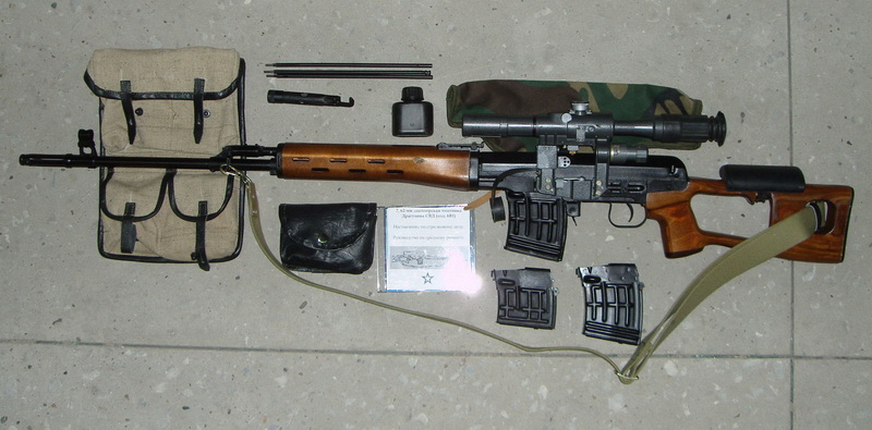
The technical description and operating instructions for the 7.62 mm Dragunov sniper rifle (SVD) are intended for studying rifles and optical sights and maintaining them in constant combat readiness.
IN this document placed technical specifications and information about the structure and operating principle of the rifle and the optical sight, as well as the basic rules necessary to ensure the correct operation of the rifle and the scope and the full use of their technical capabilities.
|
|
1.TECHNICAL DESCRIPTION
1.1. Purpose of the rifle
1.1.1. The 7.62 mm Dragunov sniper rifle (index 6B1) is a sniper weapon and is designed to destroy various emerging, moving, open and camouflaged single targets (Fig. 1).
The sniper optical sight (index 6Ts1) is used for precise aiming from a sniper rifle at various targets.
Rice. 1. 7.62 mm Dragunov sniper rifle with optical sight and bayonet:
1 - 7.62 mm Dragunov 6B1 sniper rifle. Sat;
2 - 6Ts1 optical sniper sight. ALZ. 812.000;
3 - bayonet assembly 6X5 sb
1.1.2. For shooting from a sniper rifle, rifle cartridges with ordinary, tracer and armor-piercing incendiary bullets, as well as sniper cartridges, are used. Fire from a sniper rifle is carried out in single shots.
1.1.3. The optical sight allows you to fire at night at infrared sources, as well as when unfavorable conditions lighting, when it is difficult to shoot at targets with an open sight.
When observing infrared sources, the infrared rays emitted by the source pass through the scope lens and affect the screen located in the focal plane of the lens. At the site of action of infrared rays, a glow appears on the screen, giving a visible image of the source in the form of a round greenish spot.
1.2. Technical data
1.2.1. The main design ballistic characteristics of the rifle, rifle cartridge and design data of the optical sight are given in table. 1.
Table 1
1. Caliber, mm 7.62
2. Number of grooves 4
3. Sighting range, m:
with optical sight 1300
with open sight 1200
4. Initial bullet speed, m/s 830
5. The flight range of a bullet, up to which it remains lethal action, m 3800
6. Weight of the rifle without a bayonet with an optical sight, unloaded
magazine and cheek, kg 4.3
7. Magazine capacity, 10 rounds
8. Rifle length, mm:
without bayonet 1220
with attached bayonet 1370
9. Cartridge weight, g 21.8
10. Mass of an ordinary bullet with a steel core, g 9.6
11. Mass powder charge, g 3.1
12. Magnification of the optical sight, times. 4
13. Field of view of the sight, degree 6
14. Exit pupil diameter, mm 6
15. Eye relief, mm 68.2
16. Resolution, second, 12
17. Sight length with eyecup and extended hood, mm 375
18. Sight width, mm 70
19. Sight height, mm 132
20. Sight weight, g 616
21. Weight of the sight with a set of spare parts and a cover, g 926
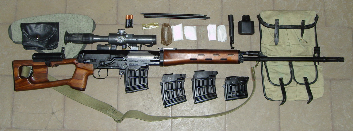
1.3. Rifle composition
1.3.1. The sniper rifle kit includes (Fig. 1):
sniper optical sight, index 6Ts1 - 1 pc.;
bayonet, index 6X5 - 1 pc.;
bag for sight and magazines (Fig. 3), index 6Ш18 - 1 pc.;
bag for spare parts (Fig. 4), index 6Ш26 - 1 pc.;
belt for carrying small arms (Fig. 5), index 6Ш5 - 1 pc.
1.3.2. The optical sniper sight is equipped with a case, a winter lighting system and individual spare parts.
1.4. Design and operation of the rifle

Rice. 2. 7.62 mm Dragunov sniper rifle:
1- frame 6B1. 2-7; 2- striker 6B1 2-5; 3- cover 6B1. Sat. 5; 4- guide rod 6B1. 5-6; 5- guide bushing 6B1. 5-5; 6- gate 6B1. 2-1; 7 - ejector axis 6B1. 2-3; 8- striker pin 6B1. 2-6; 9- ejector spring 6B1. 2-4; 10 - ejector 6B1. 2-2; 11- return spring 6B1. 5-4; 12- sighting bar clamp 6B1. 48; 13 - sighting bar 6B1. 1-21; 14- left trim assembly 6B1. Sat. 1-3; 15- pusher spring 6B1. 1-24; 16 - gas tube latch 6B1. 1-38; 17 - gas chamber 6B1. 1-15; 18 - gas piston 6B1. 1-22; 19 - gas tube 6B1. 1-25; 20 - gas regulator 6V1. 1-53; 21 - front sight body 6B1. 1-20; 22- front sight 6B1. 1-17; 23- pusher 6B1. 1-23; 24 - front sight base 6B1. 1-16; 25- barrel 6B1. 1-1; 26- upper ring assembly 6B1. Sat. 1-1; 27-ring pin 6Bl. Sat. 1-7; 28 - oil seal assembly 6B1. Sat. 1-8; 29 - right overlay assembly 6B1. Sat. 1-4; 30- lower ring with 6B1 spring. Sat. 1-5; 31—magazine body 6B1. Sat. 6-1; 32 - magazine spring 6B1. 6-12; 33 - magazine cover 6B1. 6-11; 34-bar assembly 6B1. Sat. 6-3; 35- feeder 6B1. Sat. 6-2; 36- box 6B1. 1-2; 37 - shield assembly 6B1. Sat. 3; 38 - trigger mechanism 6B1. Sat. 4; 39 - cover pin 6B1. Sat. 1-2; 40 - butt 6B1. Sat. 7
1.4.1. A sniper rifle has the following main parts and mechanisms (Fig. 2):
barrel with box;
shutter with frame;
shield assembly;
trigger mechanism;
cover with return mechanism;
shop;
butt;
upper ring assembly;
left trim assembly;
right trim assembly;
sighting bar assembly;
base and body of the front sight assembly.
1.4.2. The sniper rifle is a self-loading weapon. Reloading a rifle is based on the use of the energy of powder gases removed from the barrel bore to the gas piston.
When fired, part of the powder gases following the bullet rushes through the gas outlet hole in the barrel wall into the gas chamber, presses on the front wall of the gas piston and throws the piston with the pusher, and with them the frame, to the rear position.
When the frame moves back, the bolt opens the barrel, removes the cartridge case from the chamber and throws it out of the receiver, and the frame compresses the return springs and cocks the hammer (puts it on the self-timer).
The frame with the bolt returns to the forward position under the action of the return mechanism, while the bolt sends the next cartridge from the magazine into the chamber and closes the barrel, and the frame removes the self-timer sear from under the self-timer cocking of the hammer and the hammer is cocked. The bolt is locked by turning it to the left and inserting the bolt lugs into the cutouts of the receiver.

Rice. 3. Bag for scope and magazines 6Ш18. Sat.

Rice. 4. Bag for spare parts 6Sh26. Sat.

Rice. 5. Belt for carrying small arms 6Ш5. Sat.

Scope case
To fire the next shot, you must release the trigger and press it again. After releasing the trigger, the rod moves forward and its hook jumps behind the sear, and when you press the trigger, the rod hook turns the sear and disconnects it from the cocking of the hammer. The trigger, turning on its axis under the action of the mainspring, strikes the firing pin, and the latter moves forward and punctures the igniter primer of the cartridge. A shot occurs.
When firing the last cartridge, when the bolt moves back, the magazine feeder raises the bolt stop, the bolt rests on it and the frame stops in the rear position. This is a signal that you need to load the rifle again.
The rifle has a gas regulator, with which the recoil speed of the moving parts is changed.
Under normal operating conditions, with lubricated parts, the regulator is set to division 1. During prolonged shooting without cleaning and lubrication and the rifle is heavily soiled, a delay may occur - incomplete release of the moving parts. In this case, the regulator is switched to setting 2. The regulator is moved from one position to another using the sleeve flange or cartridge.
1.5. Design and operation of the sight and its components
1.5.1. Sniper optical sight(Fig. 6) has the following main parts:
frame;
lens;
eyepiece;
lens hood;
eyecup;
handwheel with aiming angle scale;
handwheel with lateral correction scale;
handle;
light filter in frame;
guide;
power supply;
lamp;
cap.
A lens in a frame with a retractable lens hood is screwed into the body, and an assembled eyepiece with an eyecup is screwed into the other end of the body. On top of the body there is a handwheel with an aiming angle scale printed on its cylindrical part. The handwheel nut bears the inscriptions “Up”, “Down”, “STP” and arrows indicating the direction of rotation of the handwheel when aligning the sight.
The aiming angle scale has ten divisions (from 0 to 10). The division price is 100 m. Starting from division 3, using the lock located in the handwheel, you can set aiming angles every 50 m.
On the right side of the body there is a handwheel with a lateral correction scale, on the cylindrical part of which there are 21 divisions (from 0 to 10 in both directions). The strokes and numbers located to the right of 0 are black, and those located to the left of 0 are red.
The scale division value is 0-01. Using the lock located in the handwheel, you can set corrections through O-00, 5. The nut securing the handwheel of the lateral correction mechanism has the inscriptions -Right-, -Left-, -STP- and arrows showing the direction of rotation when aligning the sight.

Rice. 6. Appearance sight PSO-1:
1- AL7 lens hood. 006.002; 2- lens in AL5.917.001 frame; 3- light filter in AL5.940.003 frame; 4- handle AL8.333.004; 5- nut AL8.373.004; 6- handwheel AL8.330.007; 7- building AL8.020.016; 8- eyepiece assembly AL5.923.010; 9- eyecup AL8.647.030; 10- cap AL6.628.000; 11- cap AL8.634.003.
There are 60 divisions on the belts of the aiming angle handwheel and the lateral correction handwheel. The division value is 0-00, 5. The divisions on the handwheel belts are used to count the correction when aligning the sight on the rifle.
The power supply for the backlight is located in the housing socket. The nest is closed with a cap.
1.5.2. The optical system of the sight is designed to create images of objects located on the ground and is a monocular telescopic system with constant magnification.
The optical system (Fig. 7) consists of objective lenses, a reticle, a wrapping system, eyepiece lenses, a screen, a light filter, a light orange filter and protective glass.
The lens is designed to construct an image of the observed object. The image of objects in the focal plane of the lens is inverted from left to right and from top to bottom.
The inverting system is designed to produce a true straight image.
The eyepiece is used to view the image of the observed object and the reticle.
The light orange filter is designed to improve the operation of the scope in cloudy weather and increase image contrast.

Rice. 7. Optical design:
1,2,3- AL7 objective lenses. 504.012, AL7.563.006, AL7.523.003; 4- welded screen 51-IK-071 Sb.14 5,6,7,8- lenses AL7.504.013, AL7.563.007, AL7.563.008, AL7.504.014 (reversing system); 9- mesh AL7.210.009; 10,11,12 - eyepiece lenses AL7.546.001, AL7.508.004, AL7.508.005; 13- light orange filter AL7.220.005; 14- light filter AL7.220 006; 15- protective glass AL8.640.004.
The mesh is a plane-parallel plate. The plate contains scales for aiming angles and lateral corrections, as well as a rangefinder scale. The view of the sight's field of view is shown in Figure 8. The aiming angle scale is made in the form of squares up to a range of 1300 m. When setting the aiming angle handwheel scale to division 10, the top of the second sighting sign on the scale from the top on the reticle will correspond to a range of 1100 m, the top of the third sign - 1200 m , and the top of the fourth is 1300 m. 
Rice. 8. View of the field of view
To the left and right of the sighting marks there is a lateral correction scale. Scale division value 0-01. The lateral correction values 0-05 and 0-10 are highlighted with an elongated stroke. The O-10 correction is marked with the number 10. To the right and left of the lateral correction scale there are two horizontal strokes.
The rangefinder scale, located on the left under the lateral correction scale, is designed to determine the range to the target. The rangefinder scale is made in the form of two lines. The top line (curve) is calculated for a target height of 1.7 m and is marked with numbers 2, 4, 6, 8 and 10.
The sight reticle moves in two mutually perpendicular directions, always remaining in the focal plane of the lens.
1.6. Rifle Accessory
1.6.1. The accessory (Fig. 9) is used for disassembling, assembling, cleaning and lubricating the sniper rifle and is carried in a bag for the scope and magazines.
1.6.2. Accessories include: cheek piece, cleaning rod, wiper, brush, screwdriver, drift, pencil case and oiler.
The cheek piece is used when shooting from a rifle with an optical sight. In this case, it is put on the butt of the rifle and secured to it with a lock.
The cleaning rod is used to clean and lubricate the bore, channels and cavities of other parts of the rifle. It consists of three links that are screwed together.
The wipe is designed to clean and lubricate the bore, as well as the channels and cavities of other parts of the rifle.
The brush is used to clean the barrel bore with a radiofrequency solution.
The screwdriver is used when disassembling and assembling the rifle, cleaning the gas chamber and gas tube, and also as a key when adjusting the position of the front sight in height.
A drift is used to push out axles and pins.
The pencil case is used to store cleaning cloths, brushes, screwdrivers and drifts. It consists of two components: a pencil case-key and a pencil case cover.
The pencil case key is used as a cleaning rod handle when cleaning and lubricating a rifle, as a screwdriver handle when disassembling and assembling a rifle, and as a key when separating the gas tube and assembling the cleaning rod.
The cover of the case is used as a muzzle pad when cleaning the barrel.
The oiler is used to store lubricant.

Rice. 9. Rifle Accessory:
1- pencil case cover 6yu7. 1-6; 2- ruff 56-Yu-212. Sat. 5; 3- screwdriver 6У7. 1; 4- rubbing 56-U-212. Sat. 4; 5- punch 56-У-212. 5: 6- pencil case body 6У7. Sat. 1-1; 7- oiler 6yu5. Sat. SB; 8- cheek 6Y7. Sat. 6; 9- cleaning rod 6Yu7. 2-1; 10- cleaning rod extension 6Yu7. 2-2; 11- front cleaning rod extension 6Yu7. 2-3
1.7. Sight accessory
1.7.1. The accessory (Fig. 10) is designed to ensure normal operation of the sight and replace individual elements that fail during operation.
1.7.2. Accessories include: case, winter lighting system, light filter in frame, key. a napkin, a lamp power source (in a cassette) and a cap.

Rice. 10 Appearance of the PSO-1 sight with an individual set of spare parts:
1- key AL8. 392.000; 2- section made of mercury-zinc elements 2РЦ63; 3- light filter AL5.940.004; 4- lamp CM 2.5-0.075 (in cassette AL8.212.000); 5- cap AL8.634.004; b- lighting system AL6.622.004
The cover is used to protect the sight from dust, rain, snow, exposure to sunlight, etc.
The winter lighting system is designed to provide illumination of the sight reticle when working with the sight in temperature conditions environment below 0 gr. WITH.
The light filter in the frame is used to operate the scope in cloudy weather.
The key is used to screw in and unscrew the reticle illumination lamp.
The cloth is used for cleaning optical parts. The power supply, lamps and cap are designed to replace failed ones.
1.8. Container and packaging
1.8.1. Sniper rifles are delivered to the consumer in wooden boxes painted in a protective color. Six sniper rifles with all accessories are placed in each box and secured with special inserts.
1.8.2. The box consists of two compartments separated by a wooden partition. The bottom, as well as all the walls of the box, are lined with waxed paper. Before capping, the bottom and walls of the large compartment of the box are additionally lined with inhibited paper. The small compartment of the box is not lined with inhibited paper, and optical sights and belts for carrying small arms sealed in this compartment are wrapped only in waxed paper.
2. OPERATING INSTRUCTIONS
2.1. General instructions
The sniper rifle and optical sight must be kept in full working order and ready for action. This is achieved by timely and skillful cleaning and lubrication, careful handling, proper storage, timely technical inspections and elimination of detected faults.
2.2. Safety instructions
2.2.1. Training in disassembling and assembling a rifle should only be done on training rifles. Training on combat rifles is permitted only in exceptional cases, subject to special care in handling parts and mechanisms.
2.2.2. Before preparing the rifle for shooting, and before cleaning and lubricating it, make sure that it is not loaded.
In front of everyone educational activities With a loaded rifle, do not point it at people or areas where people or pets may be.
Shoot in a closed shooting range only with supply and exhaust ventilation, since the powder gases released during shooting are toxic. At the end of shooting, be sure to unload the rifle and put it on safety.
2.3. Preparing a sniper rifle and optical sight for shooting
2.3.1. Preparing the rifle and scope for shooting is intended to ensure trouble-free operation during shooting. Preparing the rifle and scope for shooting is carried out in the following order:
a) clean the rifle;
b) inspect the rifle disassembled and lubricate it;
c) inspect the assembled rifle and scope;
d) check the correct interaction of parts and mechanisms of the rifle;
e) check the serviceability of the lighting system and reticle illumination;
f) check the operation of the aiming angle and lateral adjustment mechanisms of the sight;
g) check the screen is turned on and off;
h) charge the sight screen.
Immediately before shooting, wipe the barrel bore (rifling part and chamber) dry, inspect the cartridges and load the magazine with them.
To charge the sight screen, turn the screen switching handle to the position along the sight, place the sight so that the entire surface of the filter is illuminated by a light source containing ultraviolet rays.
Full charge time: in diffuse daylight - 15 minutes, in direct light sun rays and when irradiated with an electric lamp with a power of 100... 200 W at a distance of 20 cm - 7-10 minutes. Charging the screen beyond the specified time does not increase its sensitivity. A charged screen retains the ability to capture infrared rays for 6... 7 days, after which it needs to be charged again. Charging ensures operation of the sight for 3 days (when working 8 hours a day).
2. 4. Bringing the rifle to normal combat and the procedure for working with an optical sight
2.4.1. The sniper rifle located in the unit must be brought to normal combat. The need to bring the rifle to normal combat is established by checking the combat.
The rifle's combat is checked:
a) when the rifle arrives at the unit;
b) after repairing the rifle and replacing parts that could change its combat;
c) when during shooting deviations of the average point of impact (MIP) or dispersion of bullets that do not meet the requirements of normal rifle combat are detected.
In a combat situation, the rifle's combat is checked periodically at every opportunity.
2.4.2. To test the combat, fire four shots, aiming carefully and uniformly through the open sights. Shoot at a black rectangle measuring 20 cm in width and 30 cm in height, mounted on a white shield 0.5 m wide and 1 m high. The aiming point is the middle of the lower edge of the black rectangle. On a plumb line at a distance of 16 cm above the aiming point, mark with chalk or colored pencil the normal position of the midpoint of impact when shooting with open sights. This point is the control point (CT).
Firing range 100 m, sight 3. Position for shooting "prone from rest". To check the combat of a rifle and bring it to normal combat, cartridges with an ordinary bullet with a steel core are used. Shoot without a bayonet.
At the end of the shooting, inspect the target and the location of the holes, determine the accuracy of the battle and the position of the midpoint of impact.
The accuracy of a rifle's fire is considered normal if all four holes fit into a circle with a diameter of 8 cm.
If the accuracy of the holes does not satisfy this requirement, repeat the shooting. If the shooting result is unsatisfactory again, send the rifle to a repair shop.
If the combat accuracy is normal, determine the midpoint of impact and its position relative to the control point. The determination of the midpoint of impact is shown in Fig. 11.

Rice. 11. Determination of the average point of impact:
1 - sequential division of segments; 2 - with symmetrical arrangement of holes.
A rifle strike is considered normal if the average point of impact coincides with the control point or deviates from it in any direction by no more than 5 cm.
2.4.3. If, when checking the battle, the average point of impact deviated from the control point in any direction by more than 5 cm, then change the position of the front sight in height or the front sight body in lateral position. If the STP is lower than the CT, then screw in the front sight, if higher, unscrew it. If the STP is to the left of the CT, move the front sight body to the left, if to the right - to the right.
When the front sight body moves to the side by 1 mm when screwing in (unscrewing) the front sight one full turn, the STP when shooting at 100 m shifts by 16 cm.
Check the correct movement of the front sight body and front sight by shooting again. After bringing the rifle to normal combat, hammer in the old mark on the front sight body and apply a new one in its place.
2.4.4. To bring the rifle into normal combat mode with an optical sight, attach the scope to the rifle and place the cheekpiece on the butt. By rotating the handwheels, set the aiming angle handwheel to division 3, and the lateral correction handwheel to division 0.
Shoot with an optical sight under the same conditions as when checking the combat of a rifle with open sights, only mark the control point at a height of 14 cm from the aiming point. If, as a result of shooting, all four holes fit into a circle with a diameter of 8 cm, but the STP deviated from the CT by more than 3 cm, determine the deviation of the STP and make appropriate adjustments in installing the nuts on the aiming angle and lateral correction handwheels. Moving the nuts by one division relative to the scale on the handwheel belt when shooting at 100 m changes the position of the STP by 5 cm. To make adjustments, unscrew the screws on the ends of the handwheels one and a half turns, and by hand rotating the nut of the aiming angle mechanism or the nut of the lateral correction mechanism, move them to the required size and tighten the screws.
After making adjustments to the handwheel settings, fire again. If, upon repeated shooting, all four holes fit into a circle with a diameter of 8 cm, and the STP coincided with the CT or deviated from it in any direction by no more than 3 cm, then the rifle is considered to be in normal combat. Upon completion of bringing the rifle to normal combat, enter the position of the STP in the form.
2.4.5. The range to the target is determined in the following sequence:
— align the target image with the rangefinder scale of the reticle so that the base of the target is on the horizontal line of the rangefinder scale, and the top point of the target touches the upper (dotted) line of the scale without a gap;
— take a reading on the rangefinder scale at the point where the target touches;
— the number indicating the point of contact will determine the distance to the target (in Fig. 12 the distance to the target is 400 m).

Rice. 12. Rangefinder scale
2.4.6. To shoot at dusk and at night, turn the microtoggle switch to the -ON- position. In this case, set the aiming angles and lateral corrections by counting the clicks of the latch from the zero position. At the same time, remember that the handwheel fixes the aiming angles from 0 to 3 through a whole division, i.e. every 100 m, and then until setting 10 every half division, i.e. after 50 m. The lateral correction handwheel is fixed every half division, i.e. after 0-00, 5.
2.4.7. When working with a winter lighting system, the housing with section 2РЦ63 must be stored in a warm place (in the pocket of a tunic or sniper’s overcoat).
2.5. Examination technical condition, characteristic malfunctions and methods for eliminating them
2.5.1. To check the serviceability of the rifle, as well as to determine its suitability for further use, carry out periodic inspections of the rifle.
When inspecting, make sure that all parts of the rifle are present and check that the outer parts are free of rust, dirt, dents, scratches, nicks, chips and other damage that could cause disruption of the normal operation of the rifle’s mechanisms and optical sight; in addition, check the condition of the lubrication on parts visible without disassembling the rifle, the presence of magazines, a bayonet, accessories, a cover for an optical sight, a bag for a sight and magazines, and a bag for spare parts; make sure that there are no foreign objects in the bore; check the correct operation of parts and mechanisms.
When checking the correct operation of parts and mechanisms, remove the rifle from the safety lock, pull the frame back by the handle until it stops and release it; the frame should stop in the rear position by stopping the shutter. Separate the magazine, move the frame back a little by the handle and release it; The frame should forcefully return to the forward position.
Put the safety on the rifle and pull the trigger; the trigger should not move back completely, and the hammer should remain cocked. Remove the rifle from the safety and press the trigger: a click should be heard - an energetic blow of the trigger on the firing pin. Put the rifle on safety again and attach the magazine; the frame should not move back; The fuse must be securely held in position.
Check the supply of cartridges into the chamber; extraction and reflection of cartridge cases (cartridges); equip the magazine with training cartridges, attach it to the rifle and, without pressing the magazine latch, try to separate the magazine with your hand - the magazine should fit freely into the receiver window and be securely held by the magazine latch. Reload the rifle several times, while training cartridges should be sent from the magazine into the chamber without delay and vigorously thrown out of the receiver.
When checking the serviceability of the optical sight, make sure that the eyepiece and objective lenses are intact, check the smooth rotation of the handwheels and their fixation in the installed position, whether the handwheels are swaying, whether the sight is swaying and whether it is securely secured with the clamping screw on the rifle; check that the reticle lighting is working properly; to do this, put the cap on the lens, turn on the toggle switch and look into the eyepiece (if the device is working properly, the reticle is clearly visible, if the reticle is not visible, replace the battery or light bulb).
If the scope has a wobble or the bend of the handle does not fit into the cutout on the bracket when the scope is firmly attached to the rifle, adjust the clamp screw. To do this, separate the scope from the rifle, press the slider against the handle (compress the spring) and screw or unscrew the adjusting nut of the clamping screw.
Inspect the ammunition before shooting. Check them during your inspection. is there any rust or bruises on the cartridges, is the bullet loose in the barrel of the cartridge case, is there a green coating and cracks on the primer, is the primer protruding above the surface of the bottom of the cartridge case, are there any training cartridges among the live cartridges. Return all faulty cartridges to the warehouse.
2.5.2. Faults in the rifle, scope, magazines and accessories should be repaired immediately. If the malfunction cannot be resolved in the unit, send the rifle (optical sight, magazines, accessories) to a repair shop.
2.5.3. The parts and mechanisms of a sniper rifle, when handled correctly and properly cared for, work reliably and flawlessly for a long time. However, as a result of contamination of the mechanisms, wear of parts and careless handling of the rifle, as well as malfunctioning cartridges, delays in shooting may occur.
Eliminate the delay that occurs during shooting by reloading, to do this, quickly move the frame back by the handle, release it and continue shooting. If the delay persists, find out the reason for its occurrence and eliminate the delay as indicated in Table 2.
Table 2
| Name of the malfunction, external manifestation and additional symptoms | Probable Cause | Elimination method |
| The cartridge does not feed, the bolt is in the forward position, but the shot does not occur - there is no cartridge in the chamber | 1. Contamination or malfunction of the magazine 2. Malfunction of the magazine latch | If the delay occurs again, replace the magazine. If the magazine release malfunctions, send the rifle to a repair shop |
| Sticking the cartridge. The bullet cartridge hit the breech end of the barrel, the moving parts stopped in the middle position | Curvature of the bends of the side walls of the magazine | While holding the frame handle, remove the stuck cartridge and continue shooting. If the delay occurs again, replace the magazine. |
| Misfire. The bolt is in the forward position, the cartridge is in the chamber, the trigger is pulled - no shot fired | 1. Chuck malfunction 2. Malfunction of the firing pin or firing mechanism; contamination or hardening of the lubricant | Reload your rifle and continue shooting If the delay is repeated, inspect and clean the firing pin and firing mechanism; If they break or wear out, send the rifle to a repair shop |
| Failure to remove the cartridge case. The cartridge case is in the chamber, the next cartridge is buried in a bullet, the moving parts have stopped in the middle position | 1. Dirty cartridge or chamber contamination 2. Contamination or malfunction of the ejector or its spring | Pull the frame back by the handle and, holding it in the rear position, separate the magazine and remove the buried cartridge. Use the bolt or cleaning rod to remove the cartridge case from the chamber. Keep shooting. If the delay occurs again, clean the chamber. Inspect and clean the ejector and continue shooting. |
| Case sticking or non-reflection. The cartridge case was not thrown out of the receiver, but remained in it in front of the bolt or was sent back into the chamber by the bolt | 1. Contamination of rubbing parts, gas paths or chamber 2. The ejector is dirty or malfunctioning. Pull the frame back by the handle, eject the cartridge case and continue shooting. If the delay repeats, clean the gas paths, rubbing parts and chamber | If the ejector malfunctions, send the rifle to a repair shop |
2.6. Disassembling and assembling the rifle
2.6.1. Disassembly of a sniper rifle can be incomplete or complete: incomplete - for cleaning, lubricating and inspecting the rifle; full - for cleaning when the rifle is heavily soiled, after being in the rain or snow, when switching to a new lubricant and during repairs. Frequent disassembly of the rifle is not allowed, as this accelerates the wear of parts and mechanisms.
When disassembling and assembling the rifle, do not use excessive force or sharp blows.
During assembly. rifle, compare the numbers on its parts with the number on the receiver.
2.6.2. The procedure for partial disassembly of a sniper rifle:
a) separate the store. Holding the magazine with your hand, press the magazine latch and, pushing the bottom of the magazine forward, separate it. After this, check whether there is a cartridge in the chamber, to do this, lower the fuse down, move the frame back by the handle, inspect the chamber and lower the handle;
b) separate the optical sight. Lifting the clamping screw handle, turn it towards the eyecup as far as it will go, slide the sight back and separate it from the receiver;
c) separate the cheek. By turning the cheek lock latch down, remove the loop from the clip hook and separate the cheek;
d) separate the receiver cover with the return mechanism. Having turned the cover pin back until it is placed on the pin stopper screw, lift up the back part of the cover and separate the cover with the return mechanism;
e) separate the frame with the shutter. Moving the frame with the bolt back all the way, lift it and separate it from the receiver;
e) separate the bolt from the frame. Having pulled the bolt back, turn it so that the leading protrusion of the bolt comes out of the figured groove of the frame, and then move the bolt forward;
g) separate the firing mechanism. Having turned the shield up to a vertical position, slide it to the right and separate it from the receiver; holding the bracket, move downwards to separate the firing mechanism;
h) separate the barrel linings. Pressing the pin of the ring against the gas tube until the bend of the pin comes out of the cutout of the upper ring, turn the contactor clockwise until it stops; slide the top ring towards the muzzle; by pressing the lining down and moving it to the side, separate it from the barrel;
i) separate the gas piston and pusher with spring. Moving the pusher back, remove its front end from the hole of the gas piston; separate the gas piston from the gas tube; by inserting the front end of the pusher into the gas tube, press the pusher spring until it exits the channel of the aiming block, and then separate the pusher with the spring; Separate the pusher spring from the pusher.
2.6.3. The procedure for assembling a sniper rifle after partial disassembly:
a) attach the gas piston and pusher with a spring. With the pushrod spring on the rear end of the pushrod, insert the front end of the pushrod into the gas tube; Having pressed the spring, insert the rear end of the pusher together with the spring into the channel of the aiming block; move the pusher back and move its front end out of the gas tube to the side; insert the gas piston into the gas tube and the front end of the pusher into the piston hole;
b) attach the barrel linings. After inserting the rear end of the right (left) pad into the lower ring, press the pad down and fix it on the projections of the support ring; slide the upper ring onto the tips of the linings and turn the pin of the ring towards the gas tube until the bend of the pin enters the cutout on the ring;
c) attach the trigger mechanism. By placing the cutouts of the trigger mechanism housing behind the stop pin, press the trigger mechanism against the receiver; insert the axis of the shield into the hole in the receiver, and then turn the shield clockwise until the protrusion on the shield enters the lower recess of the receiver;
d) attach the bolt to the frame. Having inserted the bolt into the hole in the frame, turn the bolt so that its leading protrusion fits into the figured groove of the frame; push the shutter forward as far as it will go;
e) attach the frame with the shutter. Insert the frame guides into the receiver cutouts and slide the frame forward;
f) attach the cover with the return mechanism. Having inserted the return spring into the hole in the frame, insert the protrusions on the front end of the cover into the cutouts of the lower ring, press the rear end of the cover until it is completely adjacent to the receiver; turn the lid pin forward until it is placed on the pin stopper;
g) attach the cheek. With the cheek piece on the butt with the lock facing to the right, place the loop on the clip hook and turn the latch upward;
h) attach an optical sight. Having aligned the grooves on the sight bracket with the protrusions on the left wall of the receiver, push the sight forward as far as it will go and turn the clamping screw handle toward the lens until its bend fits into the cutout on the bracket;
i) attach the store. Having inserted the front magazine hook into the receiver window, turn the magazine towards you so that the latch slides over the rear magazine hook.
2.6.4. The procedure for completely disassembling a sniper rifle:
a) perform partial disassembly, guided by paragraph 2. 6. 2;
b) disassemble the store. Having sunk the protrusion of the locking bar into the hole on the magazine cover, slide the cover forward; holding the locking bar, remove the cover from the housing; gradually releasing the spring, remove it together with the locking bar from the magazine body; separate the feeder;
c) disassemble the return mechanism. Remove the front return spring from the guide bushing; compress the rear return spring and, holding the guide rod, move it downwards and towards you from the earring hole; separate the rear return spring and guide rod from the guide bushing;
d) disassemble the shutter. Using a punch, push out the firing pin and remove the firing pin from the bolt hole; remove the ejector with the spring in the same way;
e) disassemble the trigger mechanism (Fig. 13). Press the self-timer lever and disconnect the self-timer sear from the trigger, holding the trigger, press the trigger and smoothly release the hammer; remove the ends of the trigger spring from under the bends of the trigger mechanism housing; using a screwdriver, align the protrusions of the axes of the trigger, sear and self-timer with the cutouts for them on the right wall of the trigger mechanism housing: by pushing out the axes of the trigger, sear and self-timer, separate these parts; Having pushed out the hammer axis, separate the hammer from the mainspring, and then remove the mainspring;
f) separate the gas tube with the gas regulator. Having turned the regulator until the cutout on its front end aligns with the latch of the gas pipe, press the latch and, using a pencil case, unscrew the gas pipe and remove the regulator from it.
2.6.5. The procedure for assembling a sniper rifle after complete disassembly:
a) connect the gas pipe with the gas regulator. Having put the regulator on the gas tube, press the gas tube latch and screw the gas tube using a pencil case key until the cutout on the end of the tube matches the latch; Having sunk the latch into the cutout of the tube, set the regulator to the required division;
b) assemble the firing mechanism. Insert the trigger with its spring into the housing, insert the axle, align its protrusion with the cutout on the right wall of the case and turn the axle using a screwdriver. Place the mainspring on the hammer pins and insert the hammer into the housing.
Insert the sear into the body so that its tail goes behind the loop of the long end of the mainspring; insert axle; align its protrusion with the cutout on the right wall of the case and turn the axis using a screwdriver. Insert the self-timer into the body so that its tail goes behind the loop of the short end of the mainspring; insert the axle, aligning its protrusion with the cutout on the right wall of the case and turn the axle using a screwdriver; insert the trigger axis and place the ends of the trigger spring on the bends of the body;
c) assemble the shutter. Having inserted the ejector with the spring into the bolt socket, press the ejector and insert the ejector axis, inserting the firing pin into the bolt hole, from the side of the leading protrusion, insert the firing pin into the bolt hole and push it to the end;

Rice. 13. Trigger mechanism:
1- trigger housing 6B1. Sat. 4-1; 2-axis sear, hook and self-timer 6B1. 4-10; 3-trigger with 6B1 pull. Sat. 4-4; 4- hook spring 6V1.4-13; 5- sear 6V1.4-9V; 6- self-timer 6B1 4-23; 7- trigger 6V1.4-6; 8- combat spring 6V1.4-7; 9 - trigger axis 6V1.4-8; 10- axis of the magazine latch 6V1.4-16; 11- magazine latch 6V1.4-15; 12- magazine latch spring 6B1. 4-22.
d) assemble the return mechanism. Having inserted the guide rod into the guide bushing from the side of the large-diameter hole (with the flats forward), put the return spring on the guide bushing from the side of the rod and compress it so that the end of the guide rod with the flats comes out from under the spring; holding the guide rod in this position, insert it together with the spring and bushing into the lower hole of the earring, and then push the rod along the edges of the flats into the upper hole; release the spring - its end should enter the cup of the earring. Place the second return spring onto the guide bushing;
d) assemble a store. Having inserted the feeder and the spring into the magazine body, compress the spring until the locking bar enters the body and, holding it in this position, put the magazine cover on the body so that the protrusion of the locking bar slides into the hole in the cover;
f) carry out further assembly, guided by paragraphs, 2. 6. 3.
2.7. Cleaning and Lubrication
2.7.1. Cleaning the rifle is done:
in preparation for shooting;
after firing live and blank cartridges - immediately after the end of firing;
after the assignment and training in the field without shooting - upon returning from the assignment or training;
in a combat situation and during long-term exercises - daily during periods of calm in the battle and during breaks in exercises;
if the rifle was not used - at least once a week.
2.7.2. After cleaning, lubricate the rifle. Apply lubricant only to a well-cleaned and dry metal surface immediately after cleaning to prevent moisture from affecting the metal.
2.7.3. To clean and lubricate the rifle use:
liquid gun lubricant - for cleaning the rifle and lubricating its parts and mechanisms at air temperatures from plus 50 to minus 50 degrees C;
gun lubricant - for lubricating the barrel bore, parts and mechanisms of the rifle after cleaning them; this lubricant is used at air temperatures above plus 5 degrees C;
RFC solution - for cleaning the bore and other parts of the rifle exposed to powder gases.
Note. The RHS solution is prepared in the department in the following composition:
water suitable for drinking - 1 l;
ammonium carbonate - 200 g;
potassium dichromate (chrompic) - 3-5 g.
The solution is prepared in the amount necessary to clean the weapon within one day. Small quantity RFC solution can be stored for no more than 7 days in glass containers, sealed with a stopper, in a dark place and away from heating devices.
It is prohibited to pour RFC solution into oil cans!
rags or paper KV-22 - for wiping, cleaning and lubricating the rifle;
tow, cleared of kernels, - only for cleaning the bore.
2.7.4. Clean the rifle in the following order:
a) prepare materials for cleaning and lubrication;
b) disassemble the rifle;
c) prepare the accessory for use during cleaning;
d) clean the bore.
To clean the bore with liquid gun lubricant, place tow on the end of the wiper and lay the tow fibers along the wiper rod; Pour some liquid gun lubricant onto the tow. Insert a ramrod with rubbing and tow into the barrel bore and attach the canister cover to the flash hider. While holding the rifle, smoothly move the oakum wipe along the entire length of the bore several times. Take out the cleaning rod, change the tow, soak it with liquid gun lubricant and clean the bore several times in the same order. After this, thoroughly wipe the bore with clean, dry tow, and then with a clean rag.
Clean the barrel bore with the RFS solution using a brush soaked in the solution; then wipe the bore with tow. Continue cleaning with the RFC solution until the carbon deposits are completely removed. After cleaning the rifled part of the barrel bore, clean the chamber in the same manner; e) clean the gas chamber and gas tube using a cleaning rod or wooden stick wrapped in a rag soaked in liquid gun lubricant or RFC solution; After cleaning, wipe the gas chamber and gas pipe dry; Wipe again with a rag and inspect the bore so that there are no scraps of tow, rags or other foreign objects left in it;
f) clean the receiver, bolt frame, bolt and gas piston using a rag soaked in liquid gun lubricant or RFC solution, then wipe dry;
g) wipe the remaining metal parts dry with a rag;
h) wipe the wooden parts with a dry cloth.
2.7.5. Lubricate the rifle in the following order:
a) lubricate the bore using a wipe and a rag soaked in lubricant; lubricate the chamber;
b) lubricate all other metal parts and mechanisms of the rifle using an oiled rag;
c) apply a thin layer of lubricant, since excessive lubricant contributes to contamination of parts and can cause delays when firing;
d) do not lubricate wooden parts.
2.7.6. Assemble the rifle and check the operation of its parts and mechanisms.
2.7.7. Wipe the outer surfaces of the optical sight with a clean rag. Remove the reticle light cap and wipe the battery, housing, and cap. If the surface of the objective lenses and eyepiece are dirty, wipe them with a cloth. Lenses and glass are not allowed to be wiped with a rag that was used to wipe other parts of the sight, lubricated or touched with fingers.
It is forbidden to open the sight!
2.8. Storage and transportation rules
2.8.1. The rifle must always be stored unloaded, with the optical sight and magazine separated, the bayonet removed, the trigger pulled, the safety guard on, the sight clamp set to the -P- mark.
2.8.2. In barracks and camp situations, the rifle is stored in a pyramid; in a special compartment of the same pyramid, an optical sight in a case, magazines, a bag for the sight and magazines, a bayonet in a sheath, a bag for spare parts, a belt for carrying small arms and accessories are stored. The scope and magazine bag, case and sling should be kept clean and dry.
2.8.3. When temporarily located in a building, the rifle is stored in a dry place away from doors, stoves and heating devices. In a combat situation, keep the rifle with you, in your hands.
2.8.4. When moving to classes and on a hike, the rifle is carried on a belt. The strap must be adjusted so that the rifle does not hit the hard objects equipment. The rifle is carried with the magazine attached. The rest of the stores are in the bag.
2.8.5. When traveling in cars or armored personnel carriers, hold the rifle vertically between your knees. When traveling on tanks, hold the rifle in your hands, protecting it from hitting the armor.
2.8.6. When transported by railways or waterways, the rifle is installed in a special pyramid. If the carriage or watercraft is not equipped with pyramids, the rifle can be held in the hands or placed on a shelf so that it cannot fall or be damaged.
2.8.7. To prevent swelling or rupture of the barrel, it is prohibited to plug the bore with anything.
2.8.8. Protect the optical sight from falling, sharp blows and jolts, and from penetration of moisture and dust into the optical part; store the scope in a case in a dry, heated room; If the scope is on the rifle and you are not shooting, put a cover on the scope. Wipe the wet sight thoroughly with a dry cloth and dry the covers. It is forbidden to hold the sight near stoves and fires.
Snipers are one of the most important “castes” of any modern army. A lot depends on their actions, since in combat conditions a well-aimed shooter incapacitates enemy officers and the most active soldiers. This creates panic and forces the enemy to retreat. It's no wonder that gunsmiths pay so much attention to creating sniper rifles. Of the modern modifications, an experienced shooter can hit a target from a distance of 1.5-1.9 km! But practice shows that the first violin in a real battle is played not by such virtuosos of sniper skill, but by ordinary shooters who are armed with a simple and reliable rifle. Evgeniy Fedorovich Dragunov once created just such a weapon.
Timeless classic
In 2013, it was exactly 50 years since the legendary SVD rifle was adopted by the Soviet army. In November of the same year, information appeared that domestic gunsmiths had created a modernization kit with which the weapon was supposed to be included in the new “Ratnik” kit. The weapon gets a completely new barrel, a new receiver cover with a Piccatini rail on it. It significantly expands the range of possible “body kits” that can be installed by a fighter at any time. Vladimir Zlobin, who currently holds the post of leading designer at Izhmash, reports that a folding bipod and a telescopic butt will be added to the design.
These measures will help significantly improve the ergonomics of the weapon. After all these events, the fighters will have almost new rifle. Dragunov at one time created an excellent, without a doubt, scheme, but modern conditions have slightly different requirements for sniper weapons. Currently, there is talk about creating fundamentally new rifle systems based on the “dragunk”, which will fully meet the realities of the 21st century.
Start of work
The SVD is a fairly old rifle. Dragunov began its development back in 1958. More precisely, at that time he was entrusted with the creation of a fundamentally new self-loading weapon for the army. The choice was not accidental, since Evgeniy Fedorovich by that time had vast experience. Thanks to this, he managed to create a truly excellent and “long-lasting” rifle in the shortest possible time.

Already at the beginning of 1963, it passed all the complexes of state tests and was adopted by the SA. In just five years! Over the half century that this rifle has existed, it has literally received worldwide recognition: to date, it and its clones are in service with more than 30 countries! Even foreign experts say that the SVD is the best in its class. By the way, Western gunsmiths for a very long time had no idea about the structure of this rifle. The first copies fell into the hands of the US foreign intelligence department only in 1980, after the entry of Soviet troops into Afghanistan.
Device Basics
The rifle operates on a semi-automatic principle. Powder gases affect the automation after being removed from the barrel. Like the legendary AK, locking occurs by turning the bolt. Unlike Kalashnikov's brainchild, three lugs are used. This has a positive effect on the accuracy and accuracy of shooting. Experts believe that Evgeniy Fedorovich would have made both four and five stops, but this was prevented by the requirements of the USSR Ministry of Defense to simplify the design as much as possible so that the rifle, if necessary, could be produced at any enterprise.
In general, this rifle was not easy to create! Dragunov faced a bunch of mutually exclusive factors and demands during his work. Firstly, Evgeniy Fedorovich was tasked with creating a weapon with high shooting accuracy, but the Ministry of Defense required high reliability. It was necessary to greatly increase the gaps between the parts, and this had a very bad effect on the accuracy and accuracy... But Dragunov was able to find the ideal compromise, as a result of which his weapon is still able to compete with the best foreign self-loading rifles. Considering that the SVD, the price of which is many times lower than the cost of the main Western analogues, was produced in huge quantities, there will not be a replacement for it for a very long time.

The opinion of leading domestic experts should also be taken into account. They believe that the performance characteristics of the SVD could provide for the creation of weapons with better accuracy, if not for the requirement for maximum unification of the rifle with the AK-47. This was justified from the point of view of minimizing production costs, but did not have a very good effect on the characteristics of the product. However, SVD military snipers are quite happy, since this weapon occupies exactly the niche for which it was developed. Only absence from combat units is true sniper weapons, capable of conducting targeted fire at a distance of more than 900 meters, forces the use of the Dragunov in this role.
About accuracy and firing range
What is the standard SVD range? If a soldier is well trained, he can fire at a distance of up to 500 meters. The accuracy indicators do not exceed 1.04 arc minutes. The following types of targets (subject to the use of high-quality cartridges) can be hit at the following distances: head target - 300 meters, chest figure - up to half a kilometer, waist figure - up to 600 meters. A sniper can “picture” a running person at a distance of up to 800 meters. The rifle is equipped with a well-proven SVD PSO-1 sight, which theoretically allows firing at 1300 m. But in practice, at this distance it is only possible to hit group targets or use the rifle for harassing fire.
It is important to understand this: Dragunov rifles (SVD) do not belong to sniper weapons in the modern sense of the word. A person armed with it provides support for standard motorized rifle company at a distance of 600 meters. The shooter suppresses firing points, “takes off” grenade launchers and flamethrowers, preventing them from approaching infantry fighting vehicles and tanks within aimed shot range. Therefore, it is stupid to compare SVD and Barrett. The same American troops actively use weapons similar to it (in some places you can even find old M14s), and no complaints are made against it.
Operating principle and creation stages
As we have already said, the rifle was adopted for service in the USSR in 1963. The state competition started in 1958, at the same time it was won by a team of gunsmiths headed by Evgeniy Fedorovich. It should be noted that Kalashnikov himself participated in the competition. Mikhail Timofeevich presented to the commission a rifle created on the basis of a conventional AKM, converted for single-shot fire and with a reinforced barrel. But Dragunov’s design, in no way inferior to Kalashnikov’s brainchild in terms of reliability, was much more accurate and more accurate. Taking into account the wishes of the commission members, the gunsmith created his legendary SVD.
Ammo and scope

Since the characteristics of the standard cartridges that existed by that time did not satisfy Dragunov, a special sniper type was created. In this case, the SVD bullet has a hardened steel core, which significantly improves ballistics and penetration characteristics. Despite this, the rifle can use the entire range of 7.62x54 mm cartridges (standard SVD caliber), which were created in the USSR and the Russian Federation. Of course, shooting with machine gun ammunition shows extremely poor results. The point here is a frankly poor quality control system for this type of ammunition, when cartridges from the same batch contain completely different powder charges. The lower quality of the gunpowder itself also plays a role. This leads not only to a decrease in range, accuracy and accuracy, but also to increased contamination and wear of the weapon.
In the usual case, the SVD sight is PSO-1. It was created in 1963 specifically for the brainchild of Dragunov, and the PSO was for a long time one of the most advanced sights in the whole world; For a long time it was produced by Soviet industry in huge quantities. A special feature of this product was a successful aiming grid, which made it possible to make adjustments to the horizontal deflection “on the fly”, without resorting to adjustments using the side flywheels. This significantly increases the likelihood of a successful shot and eliminates the need to move the weapon from the aiming line.
Shooting
Few people remember this, but the SVD caliber allows the use of expansive cartridges such as JSP and JHP. Fire is only single. Ammo is fed from a detachable box magazine that holds exactly ten rounds. The weapon is equipped with a five-slot flash suppressor, which not only significantly reduces the shooter's visibility at night, but also protects the weapon barrel from contamination. The rifle also includes a gas regulator. With its help, you can adjust the recoil force of the moving parts of the weapon, which has a beneficial effect on durability and SVD. The price of the rifle itself and its spare parts is such that it turns out to be practically “eternal.” An extremely important feature for a mass, conscript army.
Stock, shortened version
The butt is a hard, skeletal type. Another feature of the SVD is the location of the fuse, as well as the receiver, which is manufactured by a simple and cheap stamping method. It also differs from most similar rifles in the standard bayonet included with the weapon. During the entire period of operation, the soldiers clearly pointed out only one drawback - the length. If we were talking about a classic sniper rifle, this value would seem completely normal, but for motorized infantry, especially airborne forces, it was unnecessary.

Therefore, during the war in Afghanistan, an SVDS with a folding stock was created, equipped with a shortened flash suppressor. It should be noted that today most combat units use this particular option. In addition, the Tula Design Bureau subsequently created a modification of the VCA (OTs-03). This is the same SVD, but converted according to the bullpup design. While maintaining the same barrel length, it is much shorter than the original. However, the troops were not delighted with this variety: it has a shorter sighting range and more pronounced recoil with the barrel being thrown up.
The automatic mode, which was the highlight of the Tula development, in reality turned out to be useless due to the terrifying recoil and the small magazine capacity of this version of the SVD. The characteristics of the IED (OTs-03) also did not satisfy the fighters of the special units of the Ministry of Internal Affairs and the FSB (for whom it, in general, was created). Basically, they are not satisfied with the characteristics of the standard 7.62x54r cartridge. The fact is that the bullet of this cartridge has too high penetration power, which is unacceptable for operations in the city and other populated areas, since this factor can lead to death or serious injury to civilians.
Automation operating principle
Powder gases are removed from the barrel through a special hole. The bolt that locks the barrel moves counterclockwise. We have already said that the SVD is equipped with three combat lugs, but this is not entirely true: the cartridge rammer is used as the third. This decision made it possible to significantly increase the area of the combat lugs without increasing their number. The result of this design decision was compact shooting from the SVD with high accuracy of the latter.

Some of the powder gases that follow the bullet enter the gas chamber, after which the pressure they create simply throws the gas piston back. The bolt frame goes along with it. At this moment, the barrel channel opens by turning the bolt, the spent cartridge case is ejected, and the bolt frame puts the trigger on cock (self-timer). The return mechanism sends the gas piston with the frame to their original position, and the bolt, using the third stop, sends a new cartridge into the chamber while simultaneously closing the channel of the latter.
The shutter turns to the left. The lugs fit into special protrusions cut into the wall of the receiver. As a weapon, the SVD is distinguished by its extreme simplicity and manufacturability. This still brings honor to Evgeniy Fedorovich.
The principle of firing a new shot
To fire again, the soldier simply needs to pull the trigger again. As soon as it is released, its pull and hook pull out the sear, it turns and disconnects from the combat platoon. The trigger hits the firing pin, which pierces the cartridge primer. This is how a new shot occurs. If it was produced by using the last cartridge, when the bolt moves back, a special stop rises, to which it clings and is fixed in the rearmost position. Simply put, the combat SVD has a bolt delay, for the absence of which some criticize the same AKM.
Other expert opinions
For its time, according to weapons experts, the rifle had excellent ergonomic characteristics: it is perfectly balanced, fits like a glove in the hands, inspiring confidence in the shooter, and is easy to hold in the line of fire. If a truly trained soldier acts as a shooter, then in a minute he can fire up to 30 targeted, well-calibrated shots. If we talk about comments regarding its length and practical range, then we discussed all these points above.
This rifle was used in all armed conflicts in which the USSR participated, and then Russian Federation, since 1963. During this time, it was highly appreciated by foreign military experts, as a result of which Dragunov clones and its derivatives ended up in service in more than three dozen countries around the world. Thus, the SVD (the characteristics of which were discussed in the article) still remains a light, reliable and widespread weapon that fully copes with the tasks for which it was created.
Large-caliber modification
Separately, I would like to dwell on the large-caliber version of the legendary rifle - SVDK. This weapon was developed precisely with the aim of getting rid of some of the shortcomings of its progenitor, leaving other characteristics unchanged. In particular, the designers wanted to achieve greater accuracy and the likelihood of hitting targets wearing body armor. Instead of the usual 7.62*54 mm cartridge, which is used in a conventional SVD, 9.3*64 mm caliber ammunition (9SN/7N33) was chosen. In general, this cartridge is unique for military practice, since it was originally a 9.3 * 64 Brenneke, used exclusively for hunting purposes.
It first appeared in Germany. This happened in 1910. The author was Wilhelm Brenneke, and the development was carried out for the Mauser bolt-action rifle. An analogue of such a cartridge is still used in domestic hunting carbines "Tiger-9", "Los-9". The resulting weapon has a lot in common with the standard SVD. Of course, there are certain differences in details, but they are associated with a different cartridge. Thus, the SVDK has a heavier barrel, a massive stamped magazine, and a bipod with mounts. The last element significantly increases the weight of the weapon, which not all shooters are unambiguous about. Some people like the increased stability, others complain about increased fatigue.

Anyway this weapon was not widely used among the troops. The culprit turned out to be Brenneke's patron. The fact is that its main positive qualities open at a distance of up to 300 meters. At this distance, the standard SVD performs excellently... As the distance increases, accuracy and accuracy drop sharply, and the penetrating qualities of the new ammunition turned out to be much lower than necessary. However, this cartridge performed well against an enemy wearing body armor, so the weapon still has prospects. However, so far the modernized SVD is performing better. This review of the rifle can be considered complete. In our article, we tried to consider all the positive and negative aspects of the weapon, which recently celebrated its half-century anniversary.
The Dragunov SVD sniper rifle, nicknamed the “whip” for the characteristic sound of a shot, is in service Russian army more than half a century and meets many modern requirements for weapons of this class.
In terms of the number of copies produced and prevalence in the world, the SVD ranks confidently in second place among sniper weapons, second only to the American M24. The rifle has become an invariable external attribute of soldiers of the Soviet and Russian armies; the only rival can be the rifle, which appeared in service 15 years earlier.
History of the Dragunov sniper rifle
The development of a specialized sniper rifle for the Soviet Army began in the second half of the 50s of the last century.
The impetus for the development was a change in the staffing of motorized rifle units, which included a sniper. The general requirements for the rifle were formalized in the form of technical specifications of the GRAU of the General Staff of the SA by 1958:
- use as ammunition (7.62*54 mm);
- have a self-loading principle of operation and not exceed the Mosin standard;
- the stock of cartridges in the store is at least 10 pieces;
- the ability to conduct effective fire at a distance of up to 600 m.
Rifles from several design bureaus, including E.F., were presented for competitive testing. Dragunova, S.G. Simonov and A.S. Konstantinov. Comparative shooting took place at the training ground in Shchurovo (Moscow region).
The samples of Simonov and Konstantinov demonstrated good automatic performance along with low combat accuracy.
The SSV-58 self-loading rifle designed by Dragunov showed high accuracy characteristics, but at the same time the commission noted the low reliability of the weapon, which became unsuitable for use after 500...600 rounds.
All three versions of the rifle received recommendations for improvement and were tested again in 1960. After this cycle of tests, Simonov Design Bureau’s weapon was considered unsuccessful (due to low accuracy compared to the standard), and the remaining two samples were sent for revision.

In particular, there were complaints about the operation of the cartridge feeding mechanism on the Dragunov rifle.
The third cycle of tests took place at the end of 1961 - beginning of 1962 and revealed the final winner - the Dragunov rifle, which surpassed its competitor in terms of fire accuracy.
Konstantinov’s weapon was rejected for the ability to fire only with an optical sight and the location of the cartridge ejection window too close to the shooter’s face.
By mid-1962, the first batch of 40 copies of the SSV-58 entered the troops. Based on operating experience, adjustments were made to the design, and in 1963 mass production of weapons began under the designation Dragunov self-loading rifle (GRAU code 6B1). At the same time, the PSO-1 model optical sight (code 6Ts1) entered service.
Early samples of the SVD had a barrel with a rifling pitch of 320 mm, which corresponded to conventional bullets and provided high accuracy parameters. When using the modernized B-32 armor-piercing incendiary bullets, increased dispersion began to be observed.
Therefore, in 1975, the pitch was reduced to 240 mm, which somewhat reduced the accuracy when using conventional bullets, but significantly improved the accuracy of fire.
Device and main characteristics
To drive the reloading mechanism, part of the powder gases is diverted from the barrel into a separate chamber with a piston. The mechanism contains a two-position gas regulator, which determines the speed of movement of the frame during rollback.
Under normal conditions, the regulator is in position 1. When using the weapon for a long time without lubrication and cleaning, delays in operation may occur. In this case, the regulator is moved to position 2 by rotating the lever with the flange part of the sleeve.
After the shot, the gases expand and push the bullet out of the barrel.
After the bullet passes through the gas outlet hole on the surface of the barrel, part of the gases enters the chamber and sets in motion the piston, made in the form of a single part together with the pusher. The pusher moves the frame to its rearmost position, compressing the return springs.
When the frame moves, the bolt opens and the cartridge case is removed from the chamber. The empty cartridge case is ejected from the cavity of the receiver and at the same time the hammer is cocked and set to self-timer mode. Then the frame reaches the stop and begins reverse movement under the force of the springs.
After the frame begins to reverse, the bolt takes the upper cartridge from the clip, feeds it into the chamber and locks the barrel. When locked, the bolt part rotates to the left, which allows the protrusions on the bolt to engage with the slots in the receiver.
Additional protrusions on the frame activate the self-timer sear rod, which moves the trigger to the firing position.
By pressing the trigger, the rod is activated, which is engaged with the sear rod. Due to this, the sear turns and releases the trigger, which begins to rotate around its axis under the influence of the force of the compressed mainspring.
The trigger strikes the firing pin and moves it forward. The sharp end of the firing pin breaks the primer and ignites the powder charge in the cartridge case.

After the last shot is fired and the frame moves to the rear point, a feeder comes out of the magazine, which turns on the shutter stop. The stop locks the shutter in the open position and prevents the frame from starting the recoil movement.
Based on the SVD, since the early 90s, it has been produced, designed to fire semi-jacketed bullets weighing about 13 grams (cartridge type 7.62 * 54R).
The weapon is used for hunting large and medium-sized animals. There are options with non-self-loading cartridges, as well as export versions chambered for .308Win (7.62*51), .30-06 Springfield (7.62*63) or 9.3*64 (Brenneke cartridge). The Tiger differs from the basic version in having a shortened barrel and a removed flash suppressor and gas regulator.
Combat use
Despite the fact that the rifle began to enter service in the 60s, it was not reported anywhere until the outbreak of hostilities in Afghanistan. After the collapse of the USSR, the rifle was used in many local conflicts in Asia, the Middle East and Africa.

Today, the 7.62 mm Dragunov sniper rifle is in service with the Russian army and the armies of several dozen countries.
Opinion about weapons
Despite the age of the weapon, it remains competitive today. Over the more than 50-year history of use, the Dragunov sniper rifle has not received any obvious negative reviews.
SVD is used by snipers in many military conflicts, despite the possibility of acquiring more modern products.
The difficulties that arise when firing at long distances are associated with incorrect calculation of the initial data by inexperienced shooters.
There are also some disadvantages of the SVD, first of all, it is a self-loading mechanism of operation, which is suitable for army snipers for shooting at distances of up to 500-600 meters, but is absolutely not suitable for sniper shooting at long distances, since the operation of the automatic system throws off the aim.

In addition, a rigid barrel mount is also noted as a disadvantage; it is believed that a floating barrel is optimal for a sniper weapon. The tide on the barrel and the bayonet itself in the rifle kit are puzzling. Sniper and bayonet attack are a rather strange combination.
The high level of performance of the rifle can be confirmed by the officially registered record for the distance to hit the target (for weapons with a caliber of 7.62 mm). This happened in 1985 in Afghanistan, when sniper V. Ilyin shot a dushman at a distance of 1350 m. The record has not been broken to this day.
Modern SVD replicas
On sale is a Dragunov air rifle manufactured by MWM Gillmann GmbH. Bullets with a caliber of 4.5 mm are installed in simulators of a real cartridge, which are located in the magazine. The gas reservoir is installed in the rifle bolt.
Thanks to this arrangement, it was possible to provide visualization of firing similar to a real weapon - with reloading and ejection of the “case” outward.
Today, work is underway to create modern sniper rifles (for example, OTs-129), but the prospects for their adoption are not clear. Therefore, for the near future, the main weapon of snipers in the Russian Army will remain the good old Russian SVD rifle.
Video
Related articles
 The best amulets against the evil eye and damage Amulet against the evil eye with hands for children
 How to read the Psalter correctly
 Delicious dishes with sausages
 A glimpse of Bella. Romantic chronicle. A glimpse of genius. Messerer about Akhmadulina Boris Messerer glimpse of Bella romantic chronicle
 I dreamed that I was sailing on a boat on the river
 How to cook beef entrecote in a frying pan
 About the company Foreign language courses at Moscow State University
 Which city and why became the main one in Ancient Mesopotamia?
 Why Bukhsoft Online is better than a regular accounting program!
 Which year is a leap year and how to calculate it